0 10v Dimming Ballast Wiring Diagram

Ot 1743 Dali Dimming Wiring Diagram Free Diagram

Ow 5590 Dimmer Lamp Wiring Diagram Wiring Diagram
Led Dimmer Switch Wiring Diagram Madura Bali Tintenglueck De

Stzln0l8tksotm

Oe 5906 Halo Light Wiring Diagram Also Lutron Grafik Eye Wiring

K4bjp1nmmpokim

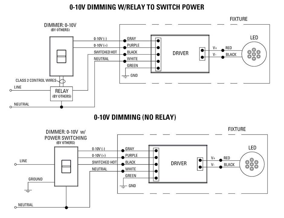
If the light output can only be dimmed from down to 10 there must be a switch or relay available to kill power to the system and turn the light.
0 10v dimming ballast wiring diagram. The 0 10v dimming wiring diagram content as well as theme of this wiring representation truly will touch your heart. It shows the elements of the circuit as streamlined forms and the power and signal connections between the devices. This is a 120v or 277 volt ballast 4435 290 32651 rev. A 0 10v dimmer is considered analog dimming and all usai 0 10v dimming options are considered to be sink type dimming.
It is the default. Collection of 0 10 volt dimming wiring diagram. 0 10v dimming ballast wiring diagram collection slerhfaceitsalon. 0 10v led fluorescent digital dimmer cat.
A wiring diagram is a simplified standard photographic depiction of an electric circuit. Our standard 0 10v dimming driver option is often provided standard check spec sheets and dims down to 10 at minimum light level. 0 10v dimming wiring diagram 0 10v dimmer switch leviton ip710 lfz or equal for other types of dimming control systems consult controls manufacturer for wiring instructions switched hot black switched hot red typical low voltage dimming wires purple gray typical electrical panel hot black typical 120v or 277v 60 hz neutral white. 0 10 v ballast driver dimming with on off control wiring diagram using relay figure c1.
Dd710 bd 120 277v 950va 120v 1350va 277v for use with fixtures using 0 10v dimmable power supply drivers advance transformer mark 7 osram sylvania quicktronic heliostm or equivalent dimmable ballasts installation instructions for non standard wiring applications refer. It shows the elements of the circuit as simplified shapes and also the power and also signal connections in between the devices. C similar to any other 0 to 10 volt dimming driver or ballast. Dimming with on off control via relay connect the control as shown in figure c2.
You can locate increasingly more experience and understanding just how the life is gone through. A philips advance mk 7 ballast izt 2s32 sc ballast install is shown here. A wiring diagram is a type of schematic which makes use of abstract photographic symbols to reveal all the affiliations of components in a system. A typical 0 10v wiring diagram is shown below.
We provide 0 10v dimming wiring diagram right here since it will certainly be so very easy for you to access the net service. A wiring diagram is a streamlined standard photographic representation of an electric circuit. Refer to the wiring sheet included with the relay for more information. Variety of 0 10v dimming ballast wiring diagram.
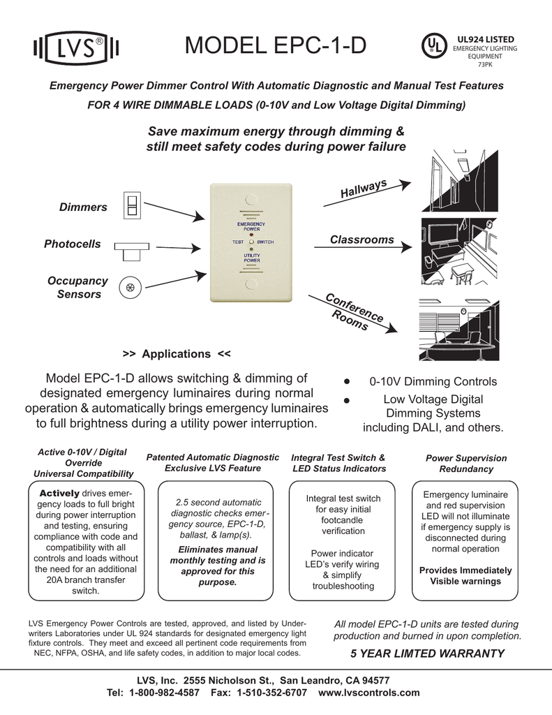
Epc 1 D Instructions

Awesome Wiring Diagram Downlights Diagrams Digramssample
D63fa Mark 10 Ballast Wiring Diagram Digital Resources
