Rb25det Tps Wiring Diagram

Vg30 Ecu Pinouts Nissan Auto Service Car Ecu

Rb25det Wiring Diagram With Images Electrical Diagram Diagram

Sr20ve Neovvl Ecu Pin Out Chart Needed Con Imagenes Coches Y
Rb25det Tps Wiring Diagram Rbdet Tps Wiring Diagram Rbdet

8 Megasquirt Wiring Harness Ms1 Ms2 Ms3 Ready Fuel Injection

Image Result For Jeep Tj Pcm Pinout Con Imagenes Esquemas
Jds performance 54 278 views.
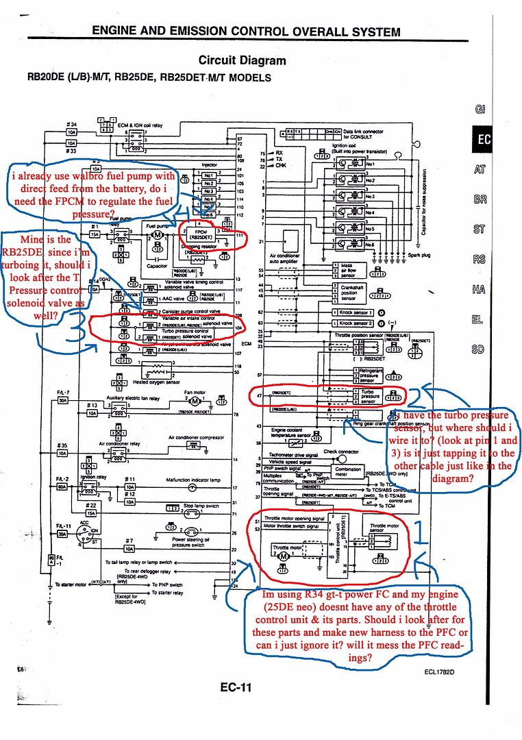
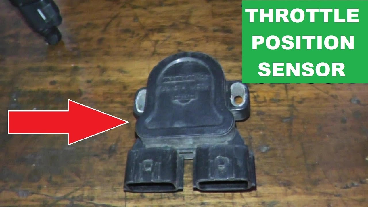
Rb25det tps wiring diagram. Universal standalone. This connector can be tested using the rb25 tps sensor wiring diagram below. Ok so me and my brother built a rb25 180sx we got the front facing plenum and the larger throttle body its been a few months now without driving the car because their are many problems with it and i just realised now we got the series 1 tps sensor because the throttle body only took the s1 tps. Home products engine management sensors position sensors tps sensors genuine nissan tps skyline r32 and r33 s1 rb20 rb25.
It was developed in house on an actual rb25det engine to ensure a perfect fit to all engine connections. Wiring specialties offers a number of options for common performance upgrades for this product. Select your chassis for wiring instructions. Rb25det turbo neo engine package fitted to s14 silvia stock js279.
Nissan silvia 180sx s13 jdm rhd. Genuine nissan tps skyline r32 and r33 s1 rb20 rb25. Wiring specialties rb26dett wiring harness. By dah hunter march 25 2019 in rb series r31 r32 r33 r34 1986 2002 recommended posts.
Nissan silvia s14 jdm rhd. Nissan skyline gts t ecr33 rb25det ecu pinout diagram pin description wire pin description wire 101 injector 1 white blue 21 serial rx yellow green 103 injector 3 white red 22 serial tx yellow 104 fuel pump control module 1 light green 23 knock sensor 1 white red 105 injector 2 yellow 24 knock sensor 2 white red. To test this insert and turn your ignition key to the on position. This harness is specifically engineered for a r32 skyline gts gts t gts 4 with the rb25det engine swap.
Nissan 240sx s13 usdm lhd. This wire heads back to pin 48 on your rb25 ecu. Classic datsun 510 z zx etc. Nissan 300zx z32.
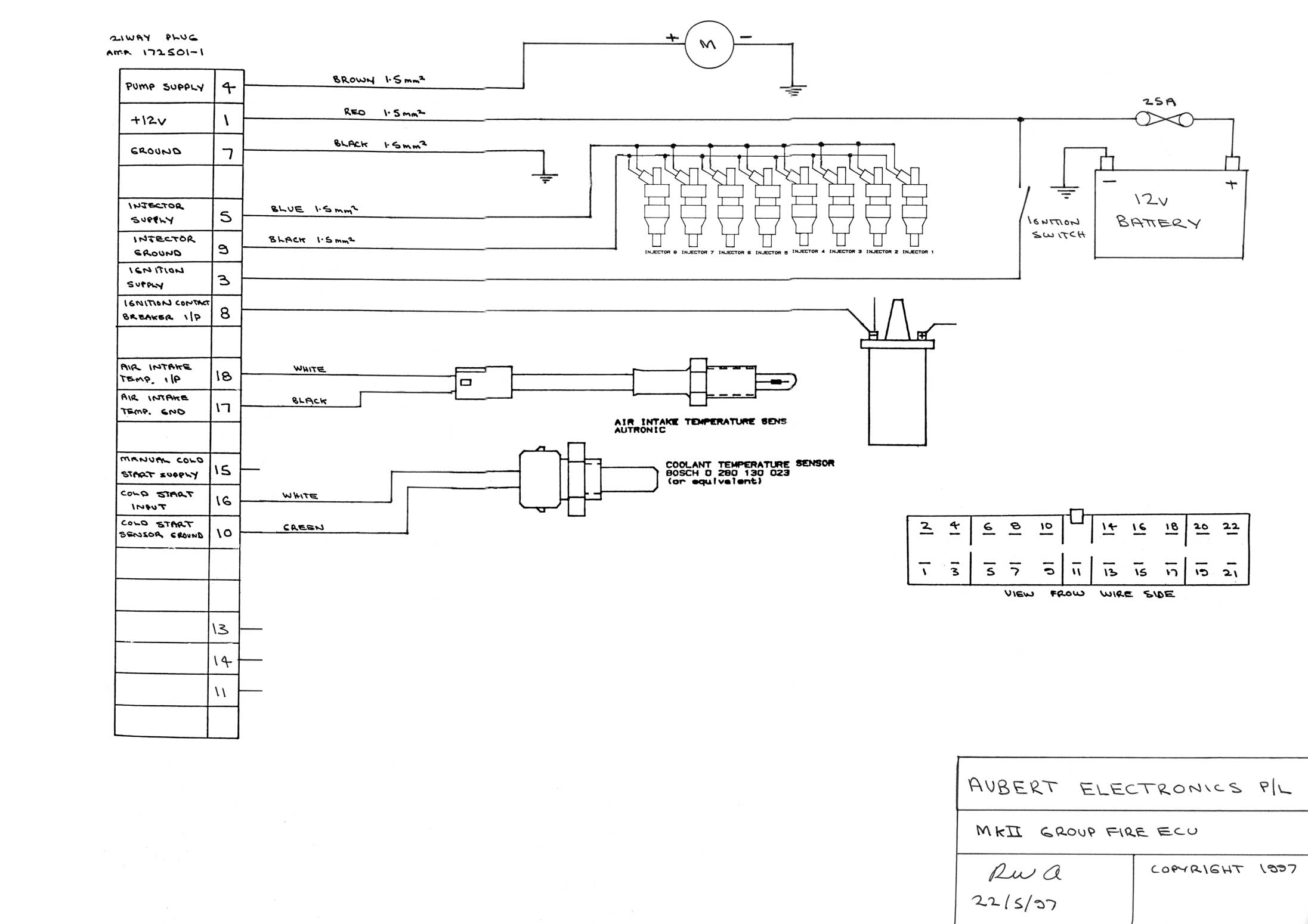
The first wire you will be starting with is the power wire. Nissan 240sx s14 usdm lhd. Nissan 200sx s13 euro lhd. Connectors sold individually connectors sets link specific wiring products.
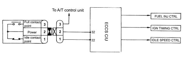
Pin 1 on the tps is 5v constant power from ecu pin 48 pin 2 on the tps is 0 5v output signal 0 5v idle 4 5v full throttle to ecu pin 38 pin 3 on the tps is earth and connected to ecu pin 30 pin 30 is also the earth for coolant temp sensor as for colour ill check a bit later see whats what. Dah hunter 1 dah hunter 1 rank. Rb25det neo auto motor tps red is the 5 volt input wire white is the tps signal wire black is the sensor return wire 1 share this post. Wiring specialties questions rb25det neo jimjamdetroit.

Pin On Auto Electrical

S100 Wiring Diagram Manualzz

861251 1 Wiring Diagram Wiring Diagram

Xlr To Rj45 Wiring Diagram Xlr Electrical Wiring Diagrams
How To Test A Rb25 Tps Sensor My Pro Street

Rb25det Ecu Wiring Skyline Owners Forum
Rb25 Bare Minimum To Get Running Driftworks Forum

Automotive Wiring Diagram Isuzu Wiring Diagram For Isuzu Npr
Wiring Diagram Page

Dodge Neon Srt4 Tps Wiring Diagram Google Search Con Imagenes

Kia Car Radio Stereo Audio Wiring Diagram Autoradio Connector Wire

Fuel Injector Info Physical Size Connector Types Sloppy

Cummins Isx Engine Wiring Diagram In 2020 With Images Cummins
